

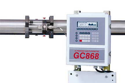
Panametrics GC868 Gas Flow Meter

- Proven Ultrasonic Technology For all natural gas flow, with the capacity to log over 43,000 flow data points
- Non Invasive Installation Specifically for metering erosive, corrosive, toxic, high-purity or sterile gases where penetrating pipe wall is undesirable
- Correlation Transit-TimeTM Demonstrated accuracy is at better than +/-2 percent of reading with +/- 0.5 percent repeatability
Case Studies
Overview
The Panametrics GC868 uses proven ultrasonic technology for all natural gas flow, fixed installation applications. It allows fast, low cost installation on existing gas mains with no need to interrupt or tamper with the gas line. This means no pressure drop, no shutdown and no regular maintenance required.
The GC868 can measure on pipes from three-quarters of an inch to 24 inch, and requires pressures from 7-barg in metal pipes. In plastic pipes, this gas flowmeter can work on ambient pressure. It comes complete with ATEX Certification.
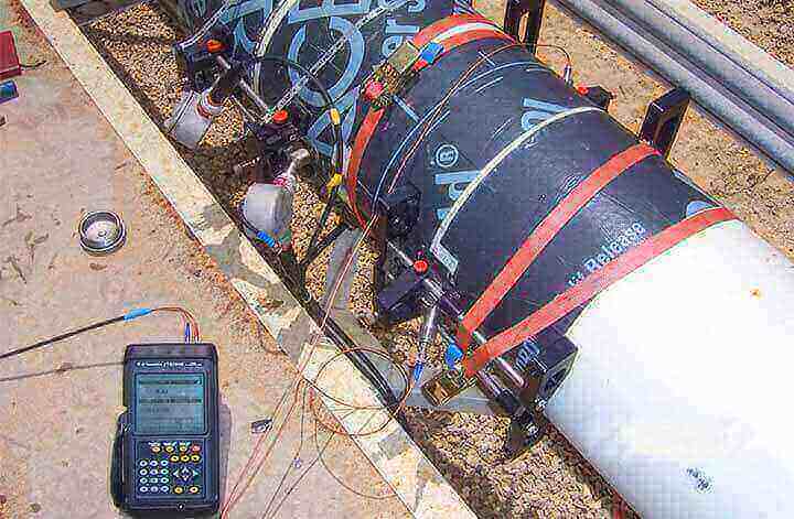
The flowmeter is comprised of the GC868 electronics, a pair of advanced clamp-on ultrasonic transducers, a clamping fixture, a preamplifier located near the transducers and coaxial cables to connect the transducers to the preamplifier and GC868 electronics. The DigitalFlow GC868 flowmeter can be used to measure the flow of any gas or steam.
Manufactured by: Panametrics
Model: Panametrics GC868 Gas Flow Meter
Services offered for this product
- Sales
- Rental
- Installation
- Calibration
- Maintenance
- IoT Cloud Compatible
Applications
Natural gas
Compressed air
Fuel gases
Erosive gases
Corrosive gases
Toxic gases
High-purity gases
Air separation gases
Steam
Specification
| Operation and Performance | |
| Fluid Types | Acoustically conductive gases with minimum density requirements (see Installation Requirements Table) |
| Pipe Sizes | - Most gases: 0.75 to 24 in NB (20 to 600 mm DN) and larger - Steam: 4 to 12 in NB (100 to 300 mm DN) |
| Pipe Wall Thickness | Thicker walled pipes require higher gas density (see Installation Requirements Table) |
| Pipe Materials | Most metals and plastics. No lined pipes. |
| Flow Accuracy (Velocity) | - For pipes 6 in (150 mm) and smaller: ±2% to 5% of reading typical - For pipes larger than 6 in (150 mm): ±1% to 2% of reading typical Accuracy depends on pipe size and whether measurement is one-path or two-path. Accuracy to ±0.5% of reading may be achievable with process calibration. |
| Repeatability | ±0.2% to 0.5% of reading |
| Range (Bidirectional) | See Installation Requirements Table |
| Rangeability (Overall) | See Installation Requirements Table |
| Specifications assume a fully developed flow profile (typically 20 diameters upstream and 10 diameters downstream of straight pipe run) and flow velocity greater than 5 ft/s (1.5 m/s). | |
| Measurement Parameters | Standard and actual volumetric flow, and flow velocity |
| Electronics | |
| Flow Measurement | Correlation Transit-Time mode |
| Enclosures | - Standard: Epoxy-coated aluminum Type 4X/IP66 Class I, Division 2, Groups A,B,C&D - Optional: Stainless steel, fiberglass, explosion-proof, flameproof II 2 G EEx d IIC T6) |
| Dimensions | Standard: Weight 11 lb (5 kg), size (h x w x d) 14.24 x 11.4 x 5.1 in (362 x 290 x 130 mm) |
| Channels | - Standard: One channel - Optional: Two channels (for two pipes or two-path averaging) |
| Display | Two independent software-configurable 64 x 128 pixel backlit LCD graphic displays |
| Keypad | 39-key, tactile-feedback membrane keypad |
| Power Supplies | - Standard: 100 to 130 VAC, 50/60 Hz or 200 to 265 VAC, 50/60 Hz - Optional: 12 to 28 VDC, ±5% |
| Power Consumption | 20 W maximum |
| Operating Temperature | -10° to 55°C (14° to 130°F) |
| Storage Temperature | -40° to 70°C (-40° to 158°F) |
| Standard Inputs / Outputs | Two 0/4 to 20 mA isolated outputs, 550 Ω maximum load |
| Optional Inputs / Outputs | There are six additional slots available for any combination of the following I/O boards: • Analog outputs: Select up to three additional output boards, each with four isolated 0/4 to 20 mA outputs,1 kΩ maximum load • Analog inputs: Select up to three boards of one of the following types: - Analog input board with two isolated 4 to 20 mA inputs and 24 V loop power - RTD input board with two isolated, three-wire, RTD inputs; span -100° to 350°C (-148° to 662°F); 100 Ω Pt • Totalizer/frequency outputs: Select up to three totalizer/frequency output boards, each with four outputs per board, 10 kHz maximum. All boards allow software-selectable functioning in two modes: - Totalizer mode: Pulse per defined unit of parameter (e.g., 1 pulse/ft3) - Frequency mode: Pulse frequency proportional to magnitude of parameter (e.g., 10 Hz = 1 ft3/h) • Alarm relays: Select up to two boards of one of the following types: - General purpose: Relay board with three Form C relays; 120 VAC, 28 VDC maximum, 5 A maximum; DC 30 W maximum, AC 60 VA - Hermetically sealed: Relay board with three hermetically sealed Form C relays; 120 VAC, 28 VDC maximum, 2 A maximum; DC 56 W maximum, AC 60 VA |
| Digital Interfaces | - Standard: RS232 - Optional: RS485 (multiuser) - Optional: Modbus® RS458 or TCP protocol - Optional: Ethernet - Optional: OPC server - Optional: Foundation fieldbus |
| Site Parameter Programming | Menu-driven operator interface using keypad and “soft” function keys |
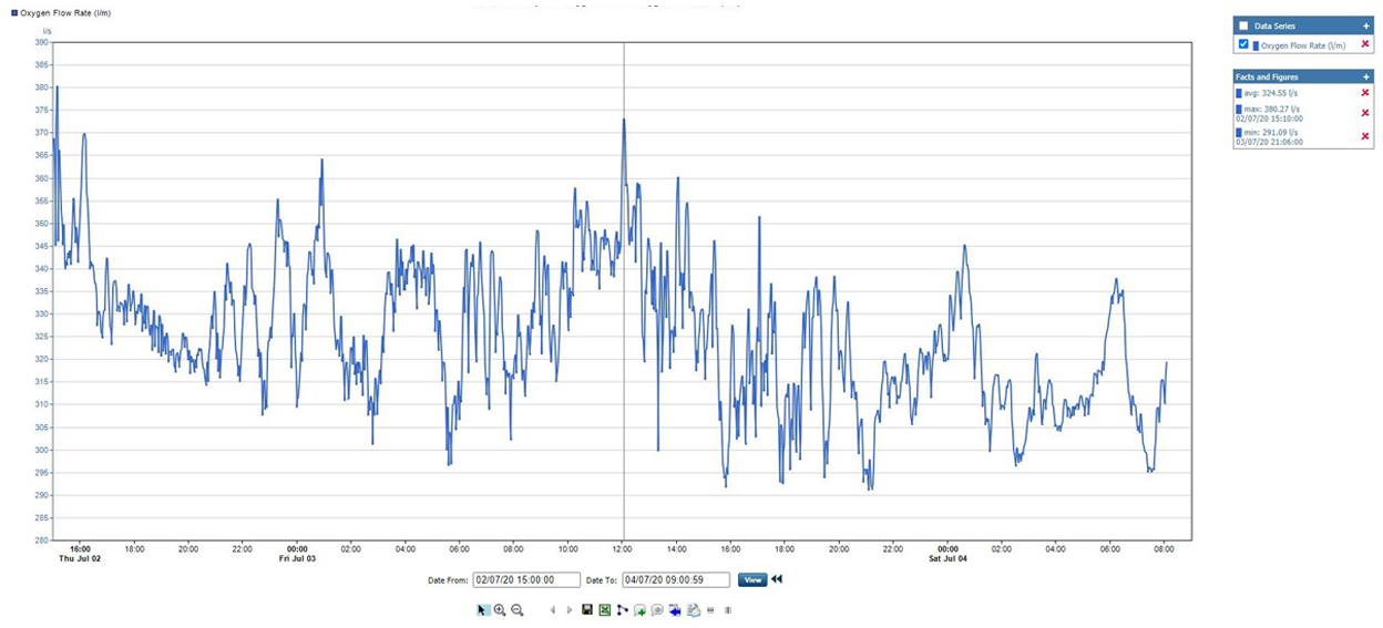
| Data Logging | Memory capacity (linear and/or circular type) to log more than 43,000 flow data points |
| Display Functions | - Graphic display shows flow in numerical or graphic format - Displays logged data and diagnostics |
| European Compliance | Complies with EMC Directive 89/336/EEC, 73/23/EEC LVD (Installation Category II, Pollution Degree 2) |
| Clamp-On Ultrasonic Flow Transducers | |
| Temperature Ranges | - Standard: -40° to 130°C (-40° to 266°F) - Optional (overall range): -40° to 230°C (-40° to 446°F) |
| Mountings | Anodized aluminum or stainless steel clamping fixture with rigid rails, chain or strap |
| Area Classifications | - Standard: General purpose - Optional: Weatherproof Type 4X/IP65 - Optional: Explosion-proof Class I, Division 1, Groups B,C,&D - Optional: Flameproof II 2 G EEx md IIC T6-T3 |